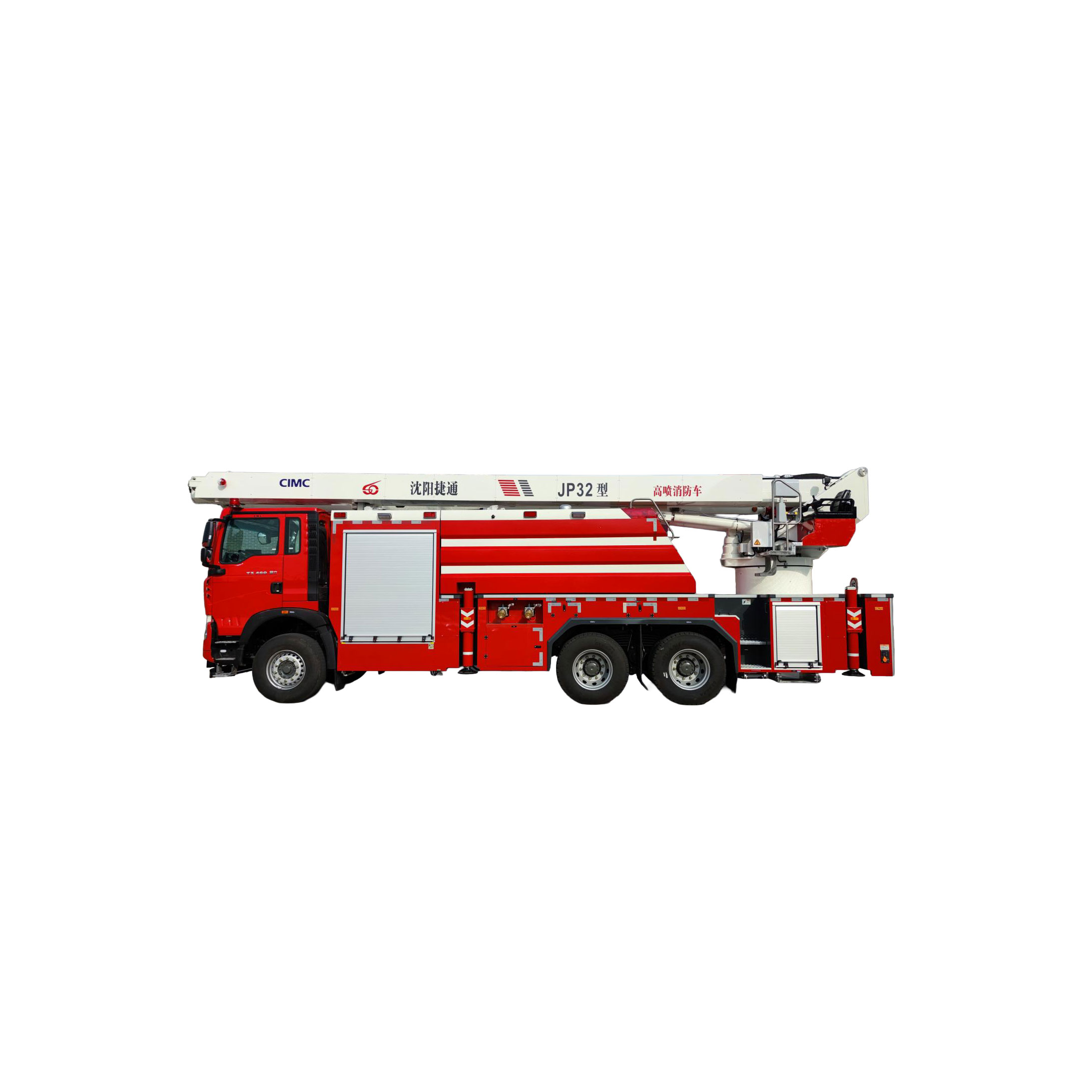
Product Introduction
The JP32 Aerial Ladder Fire Truck is an advanced high-altitude fire-fighting equipment with a maximum lifting height of 32 meters. It features a relatively small turning radius, which reduces the overall vehicle control difficulty, enabling it to adapt to various urban road conditions and neighborhoods and achieve comprehensive rescue coverage to the greatest extent. The vehicle boasts excellent passability, is equipped with a water tank, and possesses strong fire-extinguishing capabilities.
Technical Parameters
Vehicle Parameters | Dimensions: | 11271×2540×3840mm (Length × Width × Height) | ||
Total Weight | 33430kg | |||
Maximum Speed | 90km/h | |||
Chassis Parameters | Chassis Model | Sinotruk ZZ5357TXFV464MF1 | ||
Engine | MC11.46-61, Type: Inline 6-cylinder | |||
Rated Engine Power | 341Kw/1900rpm | |||
Emission Standard | National VI | |||
Maximum Allowable Total Mass of Chassis (kg) | 35000 | |||
Support System | Outriggers | Structure Type | H-type Outriggers | |
Longitudinal Span | 5630mm | |||
Lateral Span | 5820mm | |||
Leveling Method | Automatic Leveling | |||
Total Outrigger Deployment and Leveling Time | 32.1 s | |||
Maximum Working Height | 32m | |||
Maximum Working Radius | 20.9m | |||
Boom Type | Forward-inclined structure with excellent control stability: Two-section telescopic boom + Folding boom | |||
Boom Operation Method | Wired control, near-control via the operation panel on the upper vehicle console, manual multi-way valve operation | |||
Boom Luffing Angle | Lower telescopic boom: 0°——87° Upper telescopic boom relative to lower telescopic boom: 0°——166°° | |||
Slewing Range | 360° Full Rotation | |||
Time to Raise to Rated Height and Rotate 90° | 110 s | |||
Fire Water System | Fire Pump Model | Waterous (USA), Model: CXVK | ||
Rated Working Flow | Rated Flow: 100 L/S @ 1.0 Mpa Test Flow: 80 L/S @ 1.3 Mpa | |||
Fire Cannon Model | PLKD8/80 Electrically Controlled Fire Cannon by Chengdu West Fire Mechanization Co., Ltd. | |||
Maximum Range of Fire Cannon | Range (Water) ≥70m, (Foam) ≥70m. (Range varies with flow rate) | |||
Horizontal Swing Angle of Fire Cannon | ±45 degrees; | |||
Pitch Angle of Fire Cannon | Elevation angle: 45 degrees; Depression angle: -90 degrees. | |||
Tank | Material: 304 Stainless Steel | Water Capacity: 6.02 tons | Foam Capacity: 2.12 tons | |
Detailed Parameters | ||||
Chassis Parameters | ||||
Chassis Name | Sinotruk ZZ5357TXFV464MF1 | |||
Drive Form | 6×4 | |||
Wheelbase | 4600+1400mm | |||
Engine | MC11.46-61, National VI Emission, Inline 6-cylinder | |||
Rated Engine Power | 341Kw/1900rpm | |||
Transmission PTO | First Shaft PTO: HW160QZ Right Rear PTO: HW70 | |||
Transmission | Sinotruk HW25712XSTL | |||
Brake System | Service Brake | Pneumatic, Dual Circuit, Front Disc and Rear Drum Brake | ||
Parking Brake | Spring Energy Storage Air Cut-off Brake | |||
Emergency Brake | Combined with Service Brake System | |||
Auxiliary Brake | Engine Exhaust Valve Brake (EVB) | |||
Brake Force Adjustment Method | ABS | |||
Fuel Tank | 300L Steel Main Fuel Tank | |||
Tires | Non-driving Wheels: 385/65R22.5 Driving Wheels: 315/80R22.5 | |||
Generator and Battery | Rated Voltage: DC28V 28V/110A Generator, 2X12V/180AH Storage Batteries | |||
Cab | TX-D Two-door Cab, Capacity: 2 persons, Cab Color: Fire Red. Ordinary Steering Wheel, Airbag Shock-Absorbing Driver's Seat, Mechanical Passenger Seat; Electric Lifting and Tilting System, Electric Heated Rearview Mirrors, Front Electric Power Window Lifters; Sun Visor (Not available for D-type Cab), Four-point Full Floating Cab Suspension, Three-in-one Lock (Door Lock, Vehicle Start Switch, Fuel Tank Cap Lock), Nano BCU + Color Screen Instrument; Three-point Dual-lock Seat Belts, Cab Internal Control Main Power Switch, Non-slip Boarding Handrails, Dual Hydraulic Cylinder Tilting Support Structure, USB Interface, Automatic Air Conditioning, Curtain Rail, Front Lower Protection, Cruise Control, Ordinary Headlights, Daytime Running Lights. | |||
Support System | ||||
Type | H-type (Four Horizontal Outriggers, Four Vertical Outriggers)The horizontal outer sleeve is made of high-strength alloy steel profiles, and the sub-frame is a box-type structure welded by high-strength steel plates after cold bending, ensuring the safety and reliability of the support mechanism. | |||
Span | Longitudinal Span: 5630mm | |||
Lateral Span: 5820mm | ||||
Operation Form | Electric One-key Leveling, Hydraulic Manual Operation in Emergency | |||
Outrigger Position Detection System | Each outrigger is equipped with two sensors to detect the telescopic state of the outrigger | |||
Leveling Method | Automatic Leveling | |||
Manufacturing Features | All outriggers are derusted in a timely manner after welding and subjected to non-destructive testing in accordance with the requirements of GB 7956.12.The chassis connection is installed with 10.9-grade high-strength bolts. After drilling holes in the girders, the holes are anti-corrosion treated. | |||
Boom and Slewing Mechanism | ||||
Maximum Working Height | 32m | |||
Maximum Working Radius | 20.9m | |||
Slewing Mechanism | Motor-driven reducer for continuous 360° slewing. The slewing mechanism is driven by a hydraulic motor and a planetary reducer, ensuring excellent slewing stability and self-locking performance; the luffing mechanism is realized through the optimized combination of double luffing hydraulic cylinders, luffing balance valves, and bidirectional hydraulic locks, featuring good luffing synchronization and high safety. | |||
Boom Structure | It adopts a telescopic side-folding boom structure consisting of a lower boom assembly (two-section telescopic boom) and an upper boom assembly (one-section folding boom). The boom is made of high-strength alloy steel plate HQ70 through cold bending and welding. The telescopic movement of the boom is realized by telescopic cylinders to achieve the extension and retraction of each telescopic boom, and the upper boom realizes the relative luffing movement with the lower boom through cylinders. | |||
Fire Water System | ||||
Tank | Material: 304 Stainless Steel | Water Capacity: 6.02 tons | Foam Capacity: 2.12 tons | Foam Capacity: 2.12 tons |
Plate Thickness: Bottom Plate 4mm, Others 3mm | ||||
Grid-type Anti-sloshing Plates inside the tank, with longitudinal and transverse anti-sloshing plates | ||||
The water tank is equipped with a DN125 overflow pipe with an overflow cap, and the water tank is installed with an electronic liquid level gauge | ||||
The foam tank is equipped with a breather valve | ||||
The tank is elastically connected to the sub-frame | ||||
The top plate of the tank is made of non-slip stainless steel checkered plate, and the inner surface of the tank is coated with anti-corrosion paint | ||||
The water tank is equipped with 1 manhole with an inner diameter of φ440, featuring quick locking/unlocking, automatic pressure relief when the tank pressure exceeds 2 kg, and the manhole cover is painted green | ||||
Water Pump | Waterous (USA), Model: CXVK Rated Flow: 100 L/S @ 1.0 Mpa Test Flow: 80 L/S @ 1.3 Mpa Inlet Flange: DN150 | |||
Vacuum Pump | Matching Electric Vacuum Pump (24V)Vacuum Degree ≥85kPa; Suction Depth ≥7m; Priming Time <80 seconds. | |||
Mixer | Manual 95 Foam Proportioner, Mixing Ratio 3% or 6% (Optional: FSB120-C Automatic Foam Proportioner by Darley (USA), Mixing Ratio 0.5-10%) | |||
Fire Cannon | PLKD8/80 Electrically Controlled Fire Cannon by Chengdu West Fire Mechanization Co., Ltd.Rated Flow: 4800L/min, Working Pressure: 0.8Mpa, Rated Pressure: 1.0MPa.Range (Water) ≥70m, (Foam) ≥70m. (Range varies with flow rate)Horizontal Swing Angle: ±45 degrees; Elevation Angle: 45 degrees; Depression Angle: -90 degrees.Wireless Remote Control Operation ≥100 meters. | |||
Foam Cannon Head | Matching Foam Cannon Head | |||
Waterway Control | Waterway Control Method: Electromagnetic Air Valve Control | |||
Control Panel Location: Left Side of the Vehicle Body | ||||
Fire Pipeline | Lower Vehicle: Stainless Steel Pipes + Cast Aluminum Pipes | |||
Upper Vehicle: Telescopic Water Pipes, Seamless Aluminum Alloy Pipes | ||||
Optional Configurations
| For Northern Cold Regions: Waterway Purging, Electrically Heated Ball Valves at Water Outlets | |||
Water Outlet | Specification | Valve | Location | |
External Water Supply Port | 4XDN80 | Manual Ball Valve | 2 on Each Side (Left and Right) | |
External Water Suction Port | 4XDN150 | Manual Butterfly Valve with Blind Cover | 2 on Each Side (Left and Right) | |
Internal Tank Suction Port | 1XDN150 | Pneumatic Butterfly Valve | ||
Tank Water Injection Port | 1XDN65 | Pneumatic Ball Valve | ||
Water Outlet | 4XDN80 | Manual Ball Valve | 2 on Each Side (Left and Right) | |
Upper Cannon Port | 1XDN125 | Pneumatic Butterfly Valve | ||
Rear Vehicle Water Supply Port | 4XDN80 | Single-sided Flange Ball Valve | Rear of the Vehicle | |
Water Tank Drain Port | 1XDN50 Coupling DN65 | Manual Ball Valve with Coupling | ||
External Foam Suction Port | 1XDN50 | Manual Ball Valve with Blind Cover | ||
External Foam Supply Port | 1XDN50 Coupling DN65 | Manual Ball Valve with Blind Cover | ||
Foam Drain Port | 1XDN50 Coupling DN65 | Manual Ball Valve with Coupling | ||
Connection Type of Water Supply Port/Water Outlet: Internal Thread (Slow) or Quick Coupling (Fast) OptionalConnection Type of Suction Pipe: Internal Thread (Slow) or Quick Coupling (Fast) Optional | ||||
Safety Protection System | ||||
Hydraulic Filter Clogging Protection | When the filter is clogged, color or light alarm is triggered. | |||
Boom Buffer Protection | When reaching the limit position or sudden operation of the handle, the system can automatically decelerate. | |||
Boom Luffing Limit Protection | When the boom approaches the limit luffing angle, it can automatically stop slowly.。 | |||
Slewing Buffer Protection | When the slewing suddenly stops, the system can effectively achieve buffering. | |||
Slewing Centering | When the slewing approaches the neutral position, it automatically decelerates to ensure accurate alignment of the neutral position. | |||
Vehicle Anti-collision | When the boom slews at a small luffing angle, to prevent the boom from colliding with the vehicle body, the slewing in the dangerous direction is automatically stopped when the slewing reaches a certain position. | |||
Upper and Lower Vehicle Interlock | If the outriggers are not deployed, the boom cannot operate; if the boom leaves the bracket, the outriggers cannot operate. | |||
Emergency Function | Both the upper vehicle operation valve and the outrigger operation valve are equipped with emergency manual operation; the system is equipped with an emergency pump, which is used to retract the boom and outriggers when the engine or oil pump fails. | |||
Outrigger Operation Alarm | When the outriggers are operating, an audible and visual alarm is automatically triggered to prevent injury from collision. | |||
Soft Outrigger Protection | When the outrigger becomes unstable during boom operation, the operation in the dangerous direction is automatically cut off. | |||
Outrigger Not Retracted Prompt | If the outriggers are not fully retracted, an audible and visual alarm is automatically triggered to prevent accidents during driving. | |||
Waterway Overpressure Protection | When the pressure of the waterway system exceeds the rated value, an alarm is triggered and the engine acceleration is restricted. | |||
Water Tank Overpressure Protection | In addition to setting an overflow port with a sufficiently large diameter, a tank mouth pressure relief device is also provided to prevent accidental overpressure when the water tank is being filled with water. | |||
Engine Speed Limitation | When the boom is operating, the engine speed is automatically limited; when the water pump is working, the engine speed is automatically limited to prevent waterway overpressure or water pump overspeed. | |||
Excessive Wind Speed Alarm | When the wind speed exceeds 12.5 m/s, an audible and visual alarm is automatically triggered and the operation in the dangerous direction is cut off. | |||
Equipment Box Door Not Closed Prompt | If the equipment box door is not closed, an audible and visual alarm is automatically triggered to prevent accidents during driving. | |||
Sprinkler Self-protection Function | Used to protect the fire truck from high-temperature thermal radiation at the fire scene, ensuring the safety of the vehicle and firefighters | |||
Electrical System | ||||
Electric Control System | Wired remote control operation, upper vehicle console operation, outrigger operation panels located at the rear of the lower vehicle, and water pump operation panel located at the side of the lower vehicle | |||
Upper Vehicle Console | Location of Upper Vehicle Console: Left Side of the Turntable, with Seat | |||
ehicle Control | Type of Vehicle Control: Touch Screen Operation Interface or Computer Button Control | |||
Cab | 2 Round Police Lights installed on the top of the cab, Siren installed inside the cab Visual Reverse Monitor installed inside the cab, Reserved On-board Radio Interface inside the cab | |||
Fire Cannon Operation | The fire cannon can be operated and started/stopped via the wired remote control box, upper vehicle console, and fire cannon wireless remote control box. | |||
Water Pump Operation | The water pump can be operated and started/stopped via the wired remote control box, upper vehicle console, and lower vehicle operation panel. | |||
Boom Electronic Control Operation | Wired remote control box operation and upper vehicle console electronic control operationIt enables both remote control of the boom for high-altitude operations and near-control operations at the vehicle turntable. | |||
Convenient Outrigger Operation | One-key deployment and retraction via the outrigger operation panel | |||
Others | Automatic disconnection charging device; Anemometer installed on the boom; Automatic pressure stabilization control for water pump outlet | |||
Vehicle Body and Equipment Box | ||||
Compartment | The compartment surface is painted with fire red paint. To ensure safety during night operations, the vehicle body is equipped with fluorescent reflective strips that meet safety standard requirements. | |||
Color | Complies with R03 bright red in GB/T3181 "Paint Film Color Standard" specified by GB7258.The overall upper assembly and the tank crossbar are bright white. | |||
Roller Shutter Door | Adopts light high-quality aluminum alloy, large-format roller shutter door with flexible opening and closing, good sealing performance, low noise, beautiful appearance, light weight and reliability. The top is equipped with a diversion trench, and the surrounding is equipped with sealing strips, featuring excellent rainproof and dustproof sealing performance. It is equipped with a lever-type strip lock handle, a one-point pull belt and a two-point fixing seat; and a sensor is installed to check the opening and closing status of the roller shutter door through the indicator light in the cab. | |||
Equipment Box Structure | The framework is an all-aluminum alloy frame welded structure, and the outer skin adopts aluminum alloy plate bonding technology; the equipment framework inside the compartment is an aluminum alloy profile welded structure, which can flexibly layout the equipment box structure according to customer requirements to maximize space utilization. | |||
Vehicle-mounted Equipment and Documents | ||||
Vehicle-mounted Documents | Chassis Operation Manual | |||
Chassis Quality Warranty Card | ||||
Chassis Certificate of Conformity | ||||
Engine Number Rubbing | ||||
Chassis Number Rubbing | ||||
Fire Truck Operation Manual | ||||
Fire Truck Fire Equipment List | ||||
Fire Truck Certificate of Conformity | ||||
Fire Truck Follow-up Service Card | ||||
Fire Truck Handover List | ||||
Vehicle-mounted Equipment | ||||
Name | Unit | Quantity | Remarks | |
Type 20 Fire Hose | Coil | 10 | 20-80-20 (Matching the water outlet on the vehicle) | |
Type 20 Fire Hose | Coil | 4 | 20-65-20 (Matching the water outlet on the vehicle) | |
Dry Powder Fire Extinguisher | Unit | 1 | 8Kg, ABC Type Fire Extinguisher | |
Dual Water Collector | Piece | 2 | JⅡ150/80×2 | |
Water Filter | Piece | 1 | (Matching the suction pipe) | |
Suction Pipe | Meter | 8 | Four pieces of 2 meters or two pieces of 4 meters (Matching the water suction port on the vehicle) | |
Foam Suction Pipe | Root | 1 | (Matching the external foam suction port on the vehicle) | |
Reducing Adapter | Piece | 2 | 80/65 | |
Fire Hose Bridge | Pair | 2 | Rubber | |
Fire Hose Patch Cloth | Piece | 8 | ||
Fire Hose Hook | Piece | 8 | ||
ABC Wrench | Piece | 2 | ||
Suction Pipe Wrench | Piece | 2 | ||
Foam Suction Pipe Wrench | Piece | 1 | ||
Emergency Manual Wrench for Air Valve | Piece | 1 | ||
Above-ground Fire Hydrant Wrench | Piece | 1 | ||
Underground Fire Hydrant Wrench | Piece | 1 | ||
Hexagon Socket Wrench Set | Set | 1 | ||
Rubber Hammer | Piece | 1 | ||
Rechargeable Handheld Searchlight | Piece | 2 | ||
Outrigger Pad | Piece | 4 | ||
Foam Cannon Head (Foaming Tube) | Piece | 1 | Matching the model of the main boom cannon (Genuine low-expansion foaming tube) | |
Vehicle-mounted Tool Kit | Set | 1 | Provided with the chassis | |
Spare Tire | Piece | 1 | Provided with the chassis | |
Wheel Brake Block | Piece | 2 | Provided with the chassis | |
Vulnerable Parts of Hydraulic System | Set | 1 | Seals | |
Spare Parts | ||||
Name | Specification and Model | Unit | Quantity | |
Fuse | ATS2A | Piece | 1 | |
Fuse | ATS5A | Piece | 1 | |
Fuse | ATS7.5A | Piece | 1 | |
Fuse | ATS10A | Piece | 1 | |
Fuse | ATS15A | Piece | 1 | |
Fuse | ATS20A | Piece | 1 | |
Fuse | ATS30A | Piece | 1 | |
Combined Washer | ZHD-14 | Piece | 2 | |
Combined Washer | ZHD-18 | Piece | 2 | |
Combined Washer | ZHD-22 | Piece | 2 | |
Combined Washer | ZHD-27 | Piece | 2 | |
Combined Washer | ZHD-33 | Piece | 2 | |
Combined Washer | ZHD-42 | Piece | 2 | |
Compression Fitting | 2C9-18 | Piece | 1 | |
Compression Fitting | 1DM-36-27WD | Piece | 1 | |
Compression Fitting | 1DM-36-33WD | Piece | 1 | |
Compression Fitting | CC-18 | Piece | 1 | |
Compression Fitting | 1CB-18-08WD | Piece | 1 | |
Compression Fitting | 1CB-36-16WD | Piece | 1 | |
Compression Fitting | 1DB-36-16WD | Piece | 1 | |
Compression Fitting | 1C-18 | Piece | 1 | |
Oil Cup | M10×1_Straight | Piece | 1 | |
Oil Cup | M10×1_90°Elbow | Piece | 1 | |
Oil Cup | M10×1_45°Elbow | Piece | 1 | |
Oil Cup | M8×1_90°Elbow | Piece | 1 | |
O-Ring | GB/T3452.1_20X2.65 | Piece | 2 | |
O-Ring | GB/T3452.1_12X2.65 | Piece | 2 | |
O-Ring | GB/T3452.1_14X2.65 | Piece | 2 | |
High Stability
The aerial ladder fire truck adopts a forward-inclined structure for the upper and lower booms, ensuring excellent control stability. This structure can offset the recoil force generated when the water cannon is in operation, significantly enhancing the boom stability with minimal swing range and supporting 360° full rotary operation.
Maneuverability
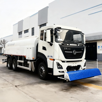
It is built on the Sinotruk ZZ5357TXFV464MF1 chassis with a 3-axle structure and a small turning radius, making it suitable for shuttling through cities and conducting high-altitude fire-fighting and rescue operations.
Water System Performance
It offers three optional water supply functions: boom external water supply, automatic water receiving and supply, and coupled water supply. It can receive external water supply from water tankers, be filled with water from fire hydrants, or directly draw water for fire extinguishing through the water suction port, meeting various operational requirements.
Advanced Outrigger Structure
The overall structure is optimized using multiple software such as SolidWorks and ANSYS, followed by actual stress testing. The traditional H-type outrigger structure has a maximum lateral deployment span of only 6m; when a single-side outrigger is deployed, it occupies only 4.25 meters of space while ensuring maximum single-side operation range. The outrigger operation panels are located on both sides of the vehicle rear, allowing for better observation of the surrounding environment during outrigger operation.
Easy-to-Maintain Telescopic Chain Structure
It adopts a plate chain structure, which is easy to install and maintenance-free; in contrast, the steel wire rope structure requires regular maintenance, additional anti-loosening devices, leading to higher failure rates and cumbersome operation.